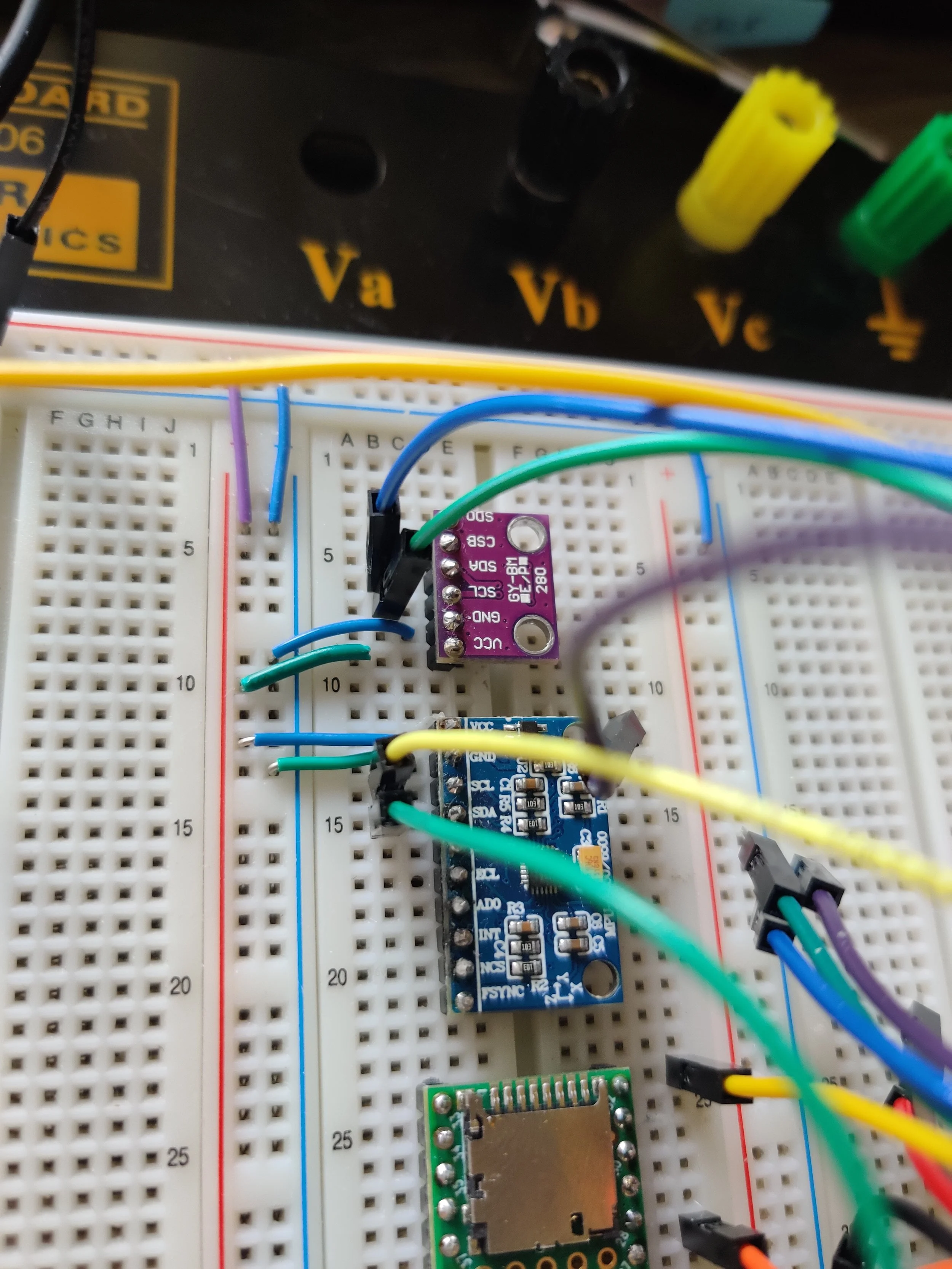
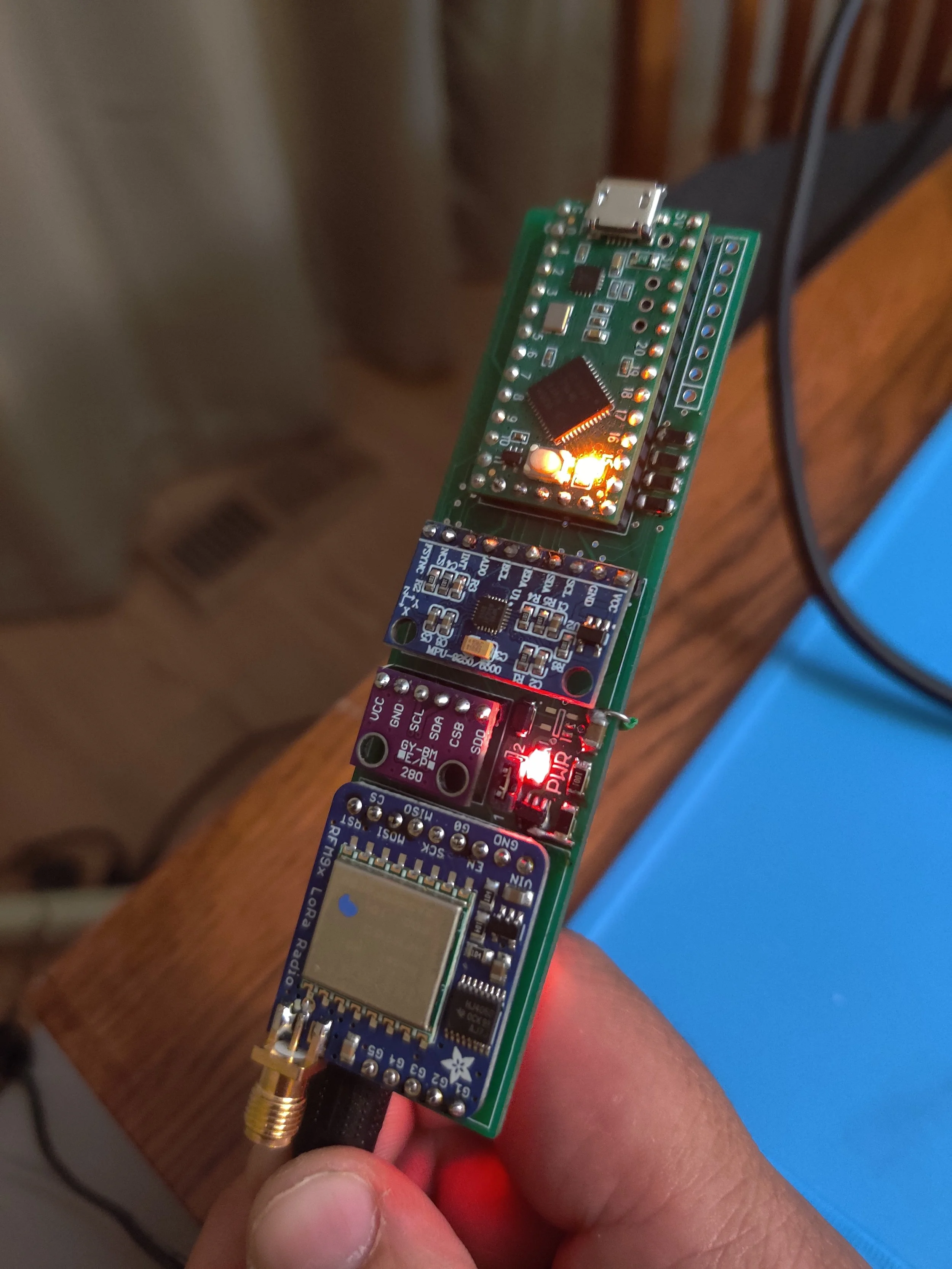
Rocketry Avionics Computer
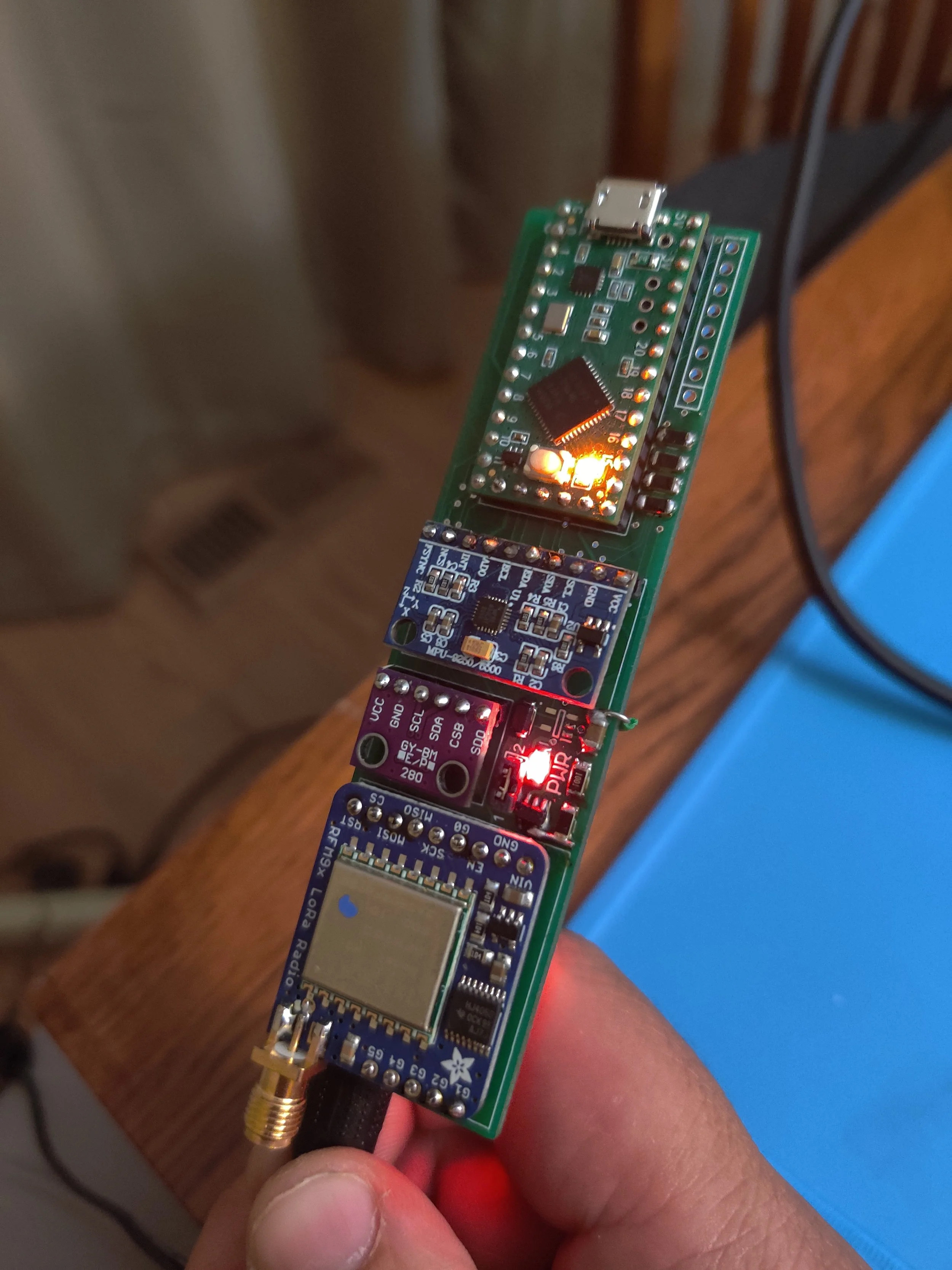
REV 0 (Modules Mounted to PCB interconnections)
I am currently part of a small model rocket hobby club in which I am the sole electronics designer. As such I am tasked with building a custom pcb that we can use to fulfill all of our desired requirements and hopefully not break our banks. It also means that I do not have access to more precise and industrial manufacturing or design tools. This project is also broken into two distinct parts in a pre-masters program design, and a post-masters design. The first using circuit maker and being functional with errors, the second being designed to my own personal standards now that I have a much better understanding than my undergraduate self.
The requirements for this board being:
Easy to flash
Non-proprietary and debuggable by design
Hand solderable with a stencil and hot air
Dual core and high speed as to rapidly measure status and deploy at apogee, while streaming a video feed and location data down to earth from a connected GPS.
C++ compatible
Accurate to GPS data
REV 1 (Functional and Flashable, but Hidden Errors Prove Fatal)
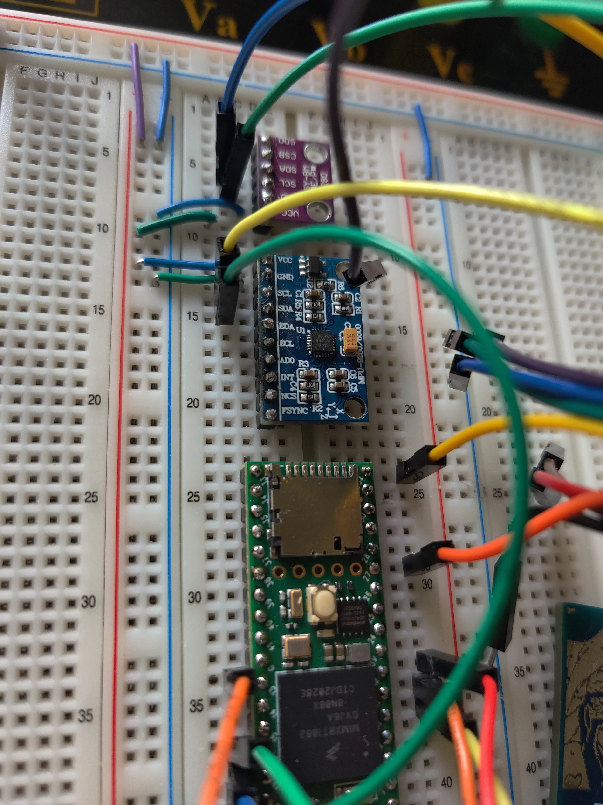
The first board, designed before I understood RF or antenna design, and before I could hand solder sizes smaller than 1206, was created in late 2023. It features a design based on the Teensy 4.1 board with its blazing fast NXP mcu. It successfully flashed the teensy Bootloader both for c++ and CircuitPython, and the digital IO was fully functional in deploying the detonations at designated marks. However, my implementation of logic level shifting from 5V down to 3.3V contained a severe wiring fault as a result of circuit maker’s always-online cloud system disconnecting the bridge connections between schematics pages. An error I should’ve seen in layout, but did not. As such the sensors have no method of reporting back, and without proper breakout pads, I could not make proper bridges.
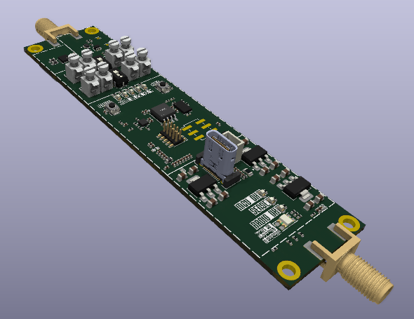
REV 2 (Currently in Prototyping/Verification Phase)
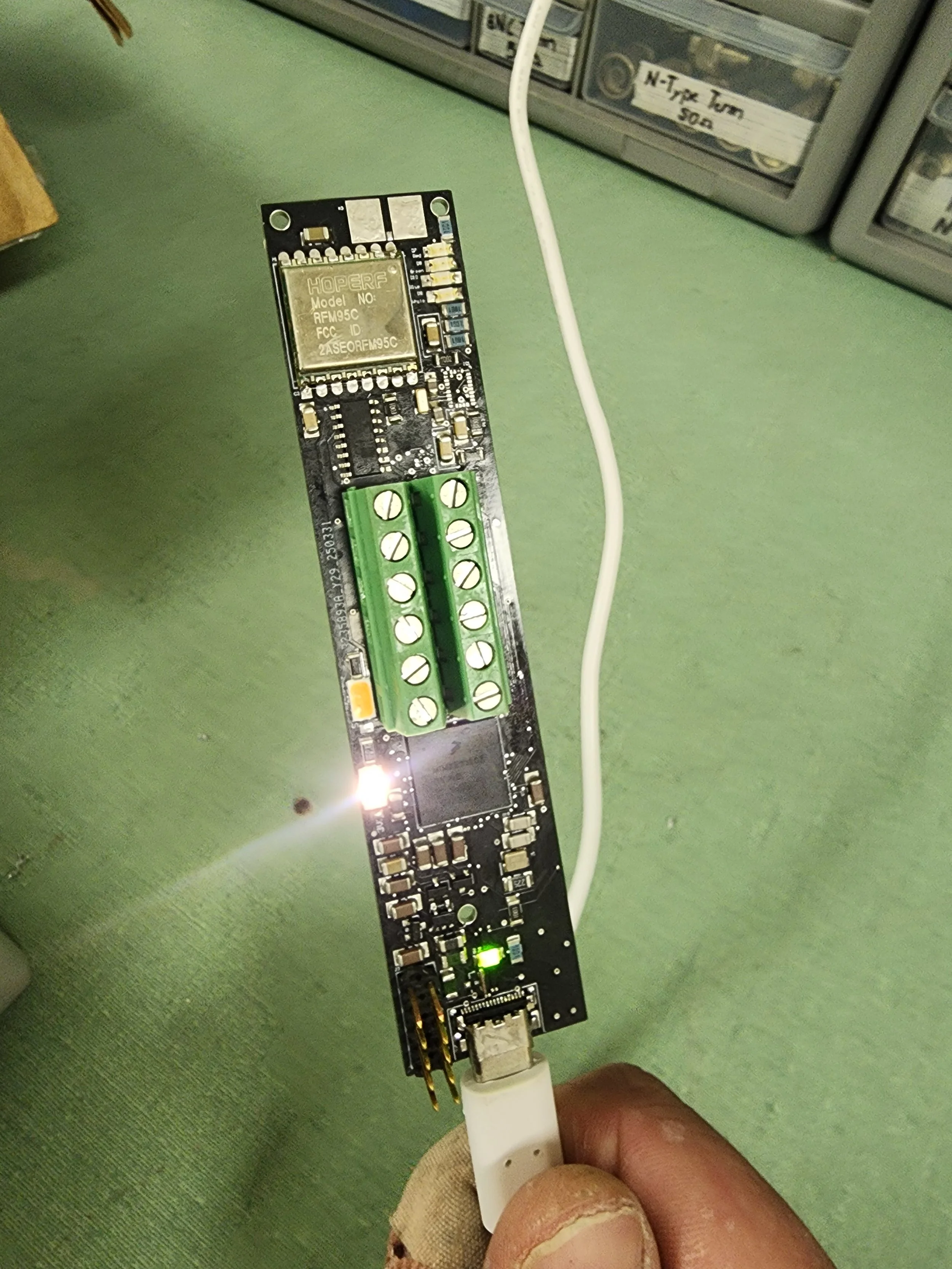
Revision 2 features designs based on the chipsets themselves, focussing on adherence to data sheet designs and recommendations as well as extensive testing for flashing custom boot loaders and firmware compatibility. GPS module is also appended onto the board now and no longer is separate as a module. Additionally while still communicating with a transceiver utilizing a lora module, the antenna has been swapped out to an optimized on-rocket form as opposed to the monopole used prior. Most importantly, it utilizes an easily flushable generic dual-core stm32h7 at 480[MHz]. This loss in speed being made up with the huge gain of me being able to hand debug and solder all of the leads, an issue with the bga format. Currently waiting for tariffs to cool off in order to order the board and components.
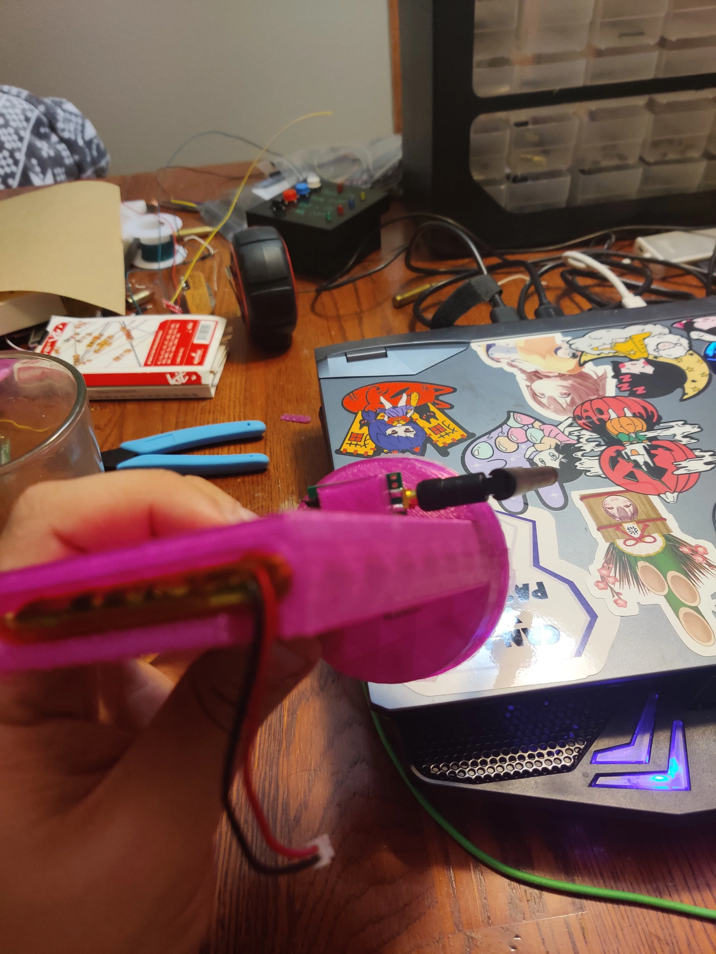
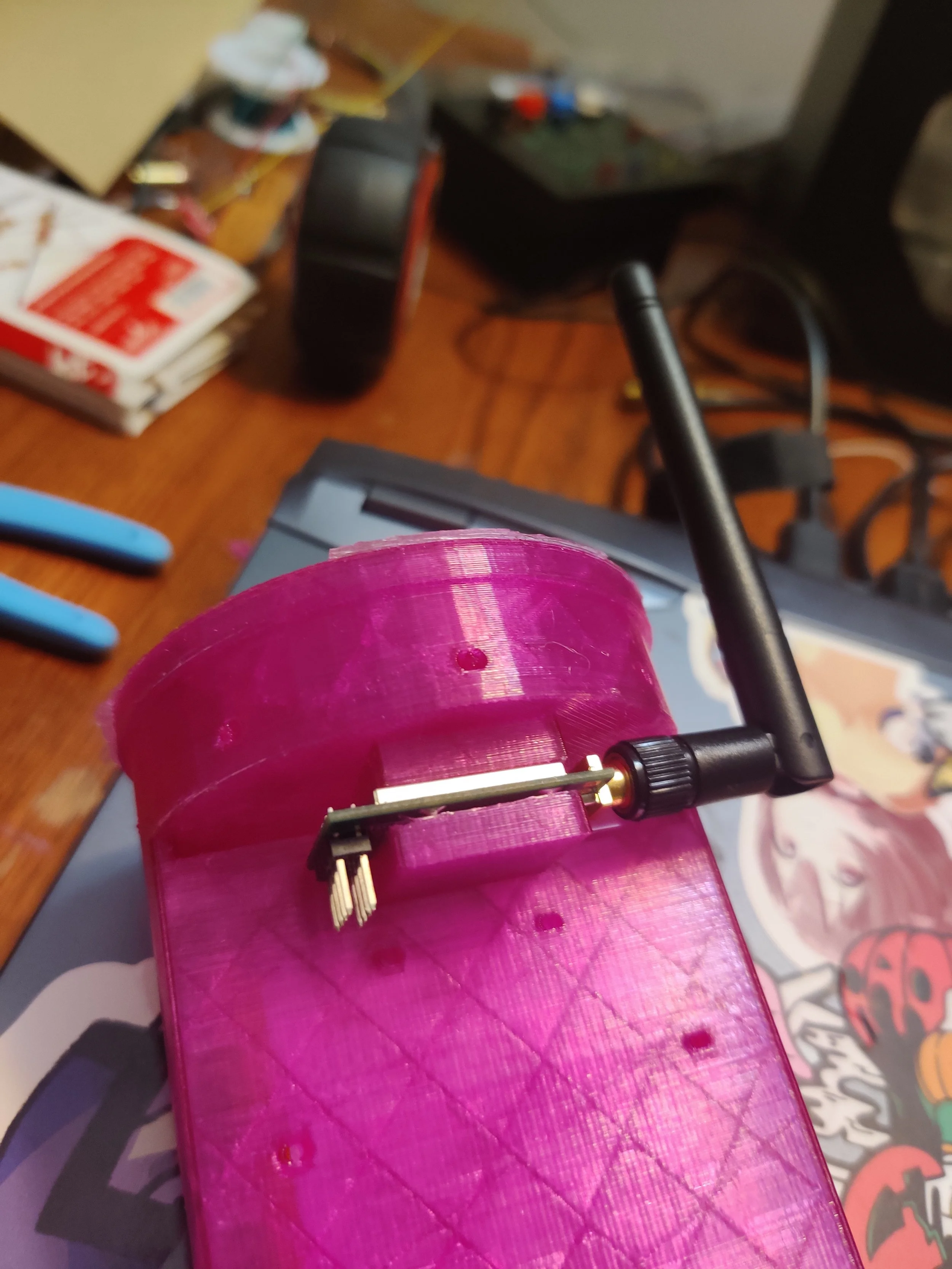
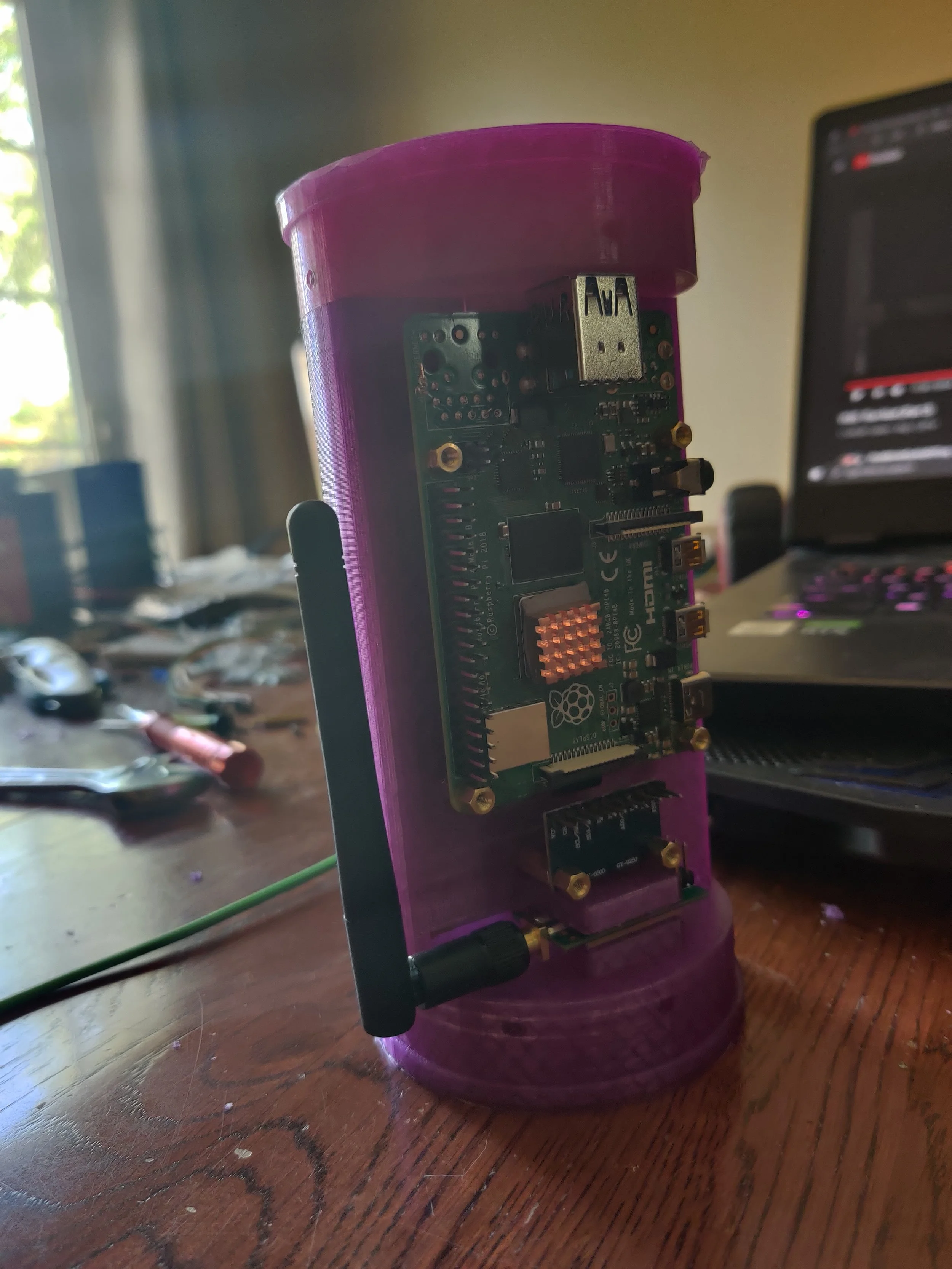
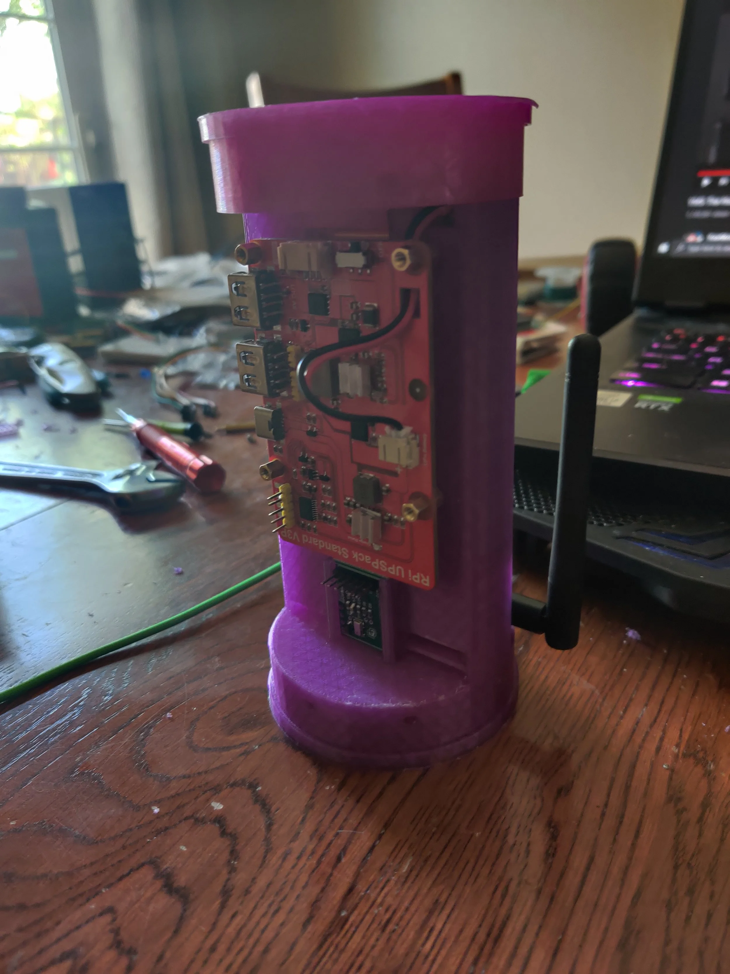
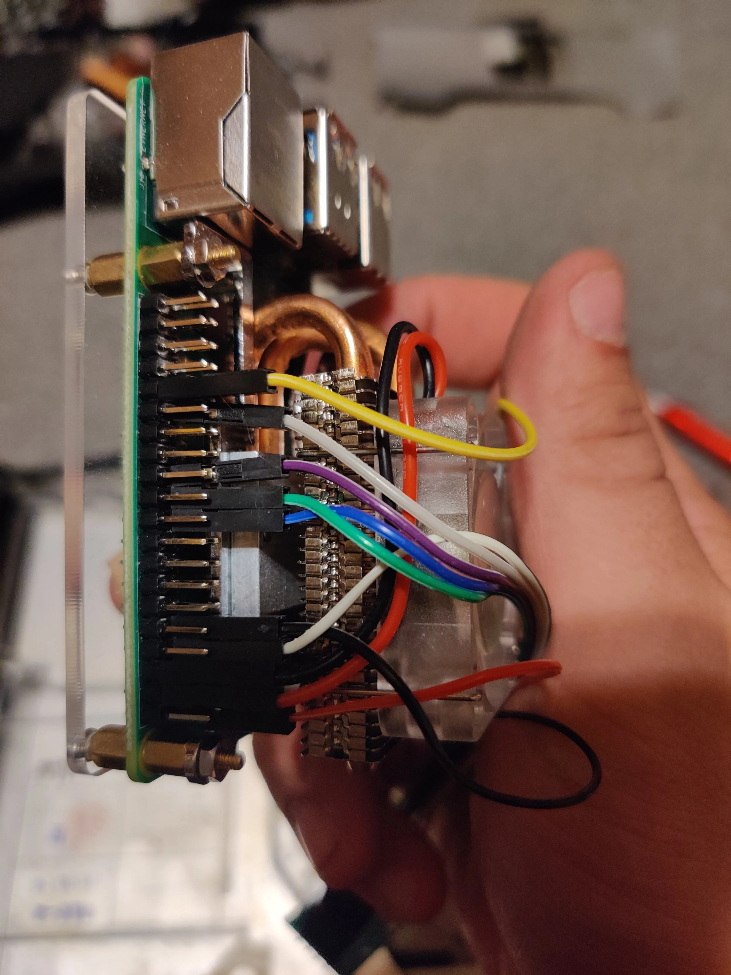
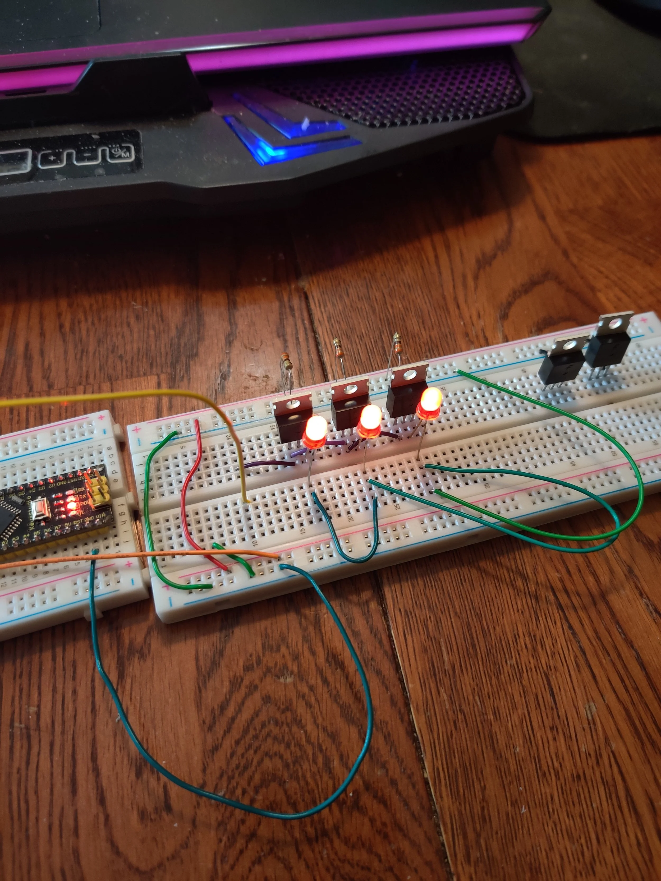
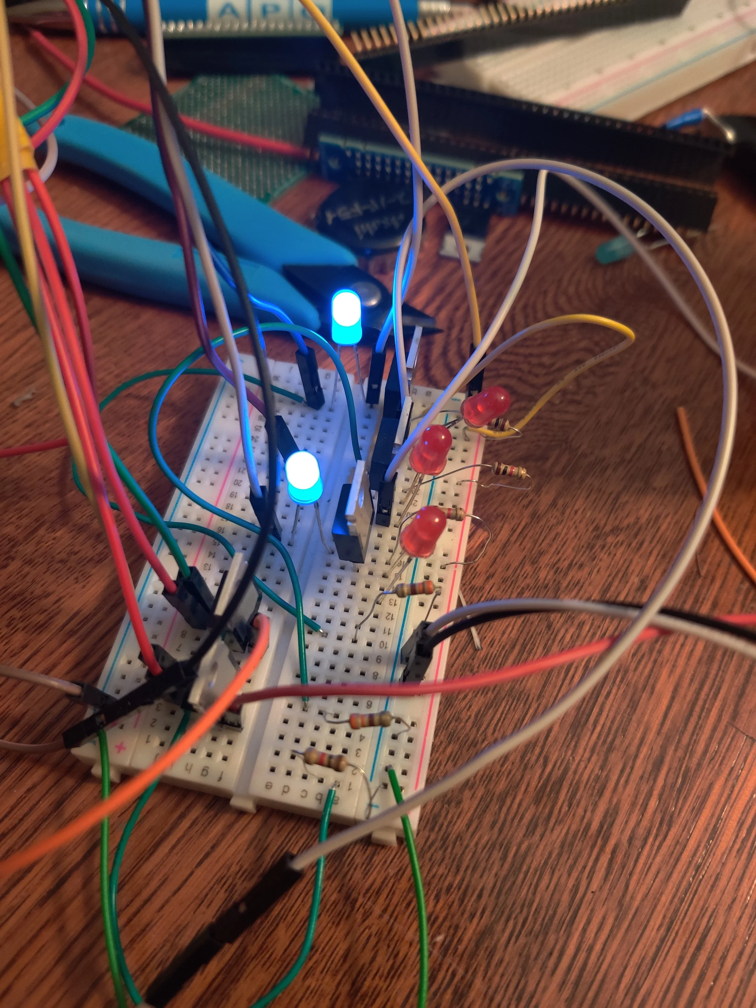
Included below are conceptual designs from our first rocket launch that used a raspberry pi. Unfortunately, while we tested and verified everything as a system while on the ground, due to suspected loose connections (pressure fit pin connections not soldered), it did not survive the test flight.