Antenna Catalogue
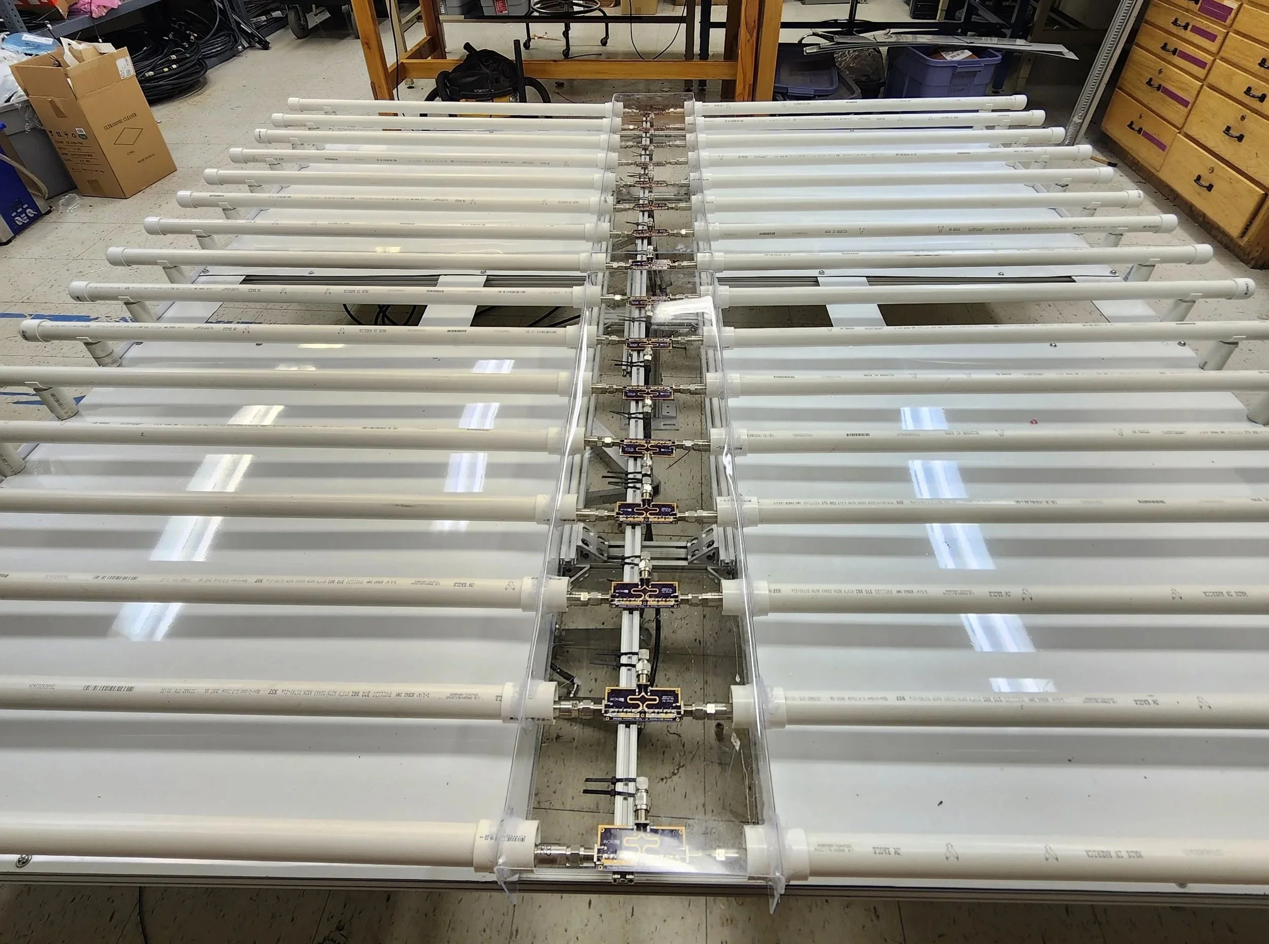
The Coaxial Collinear AESA
In terms of array-based active antenna systems, the coaxial collinear array is both the easiest to design and build. Using the definition of phased arrays, it works by progressively adding a fixed phase shift to each successive element, all of which are approximately half a wavelength apart to provide maximum gain. This linear array is stacked as a pair and can be driven either as two independent linear arrays, or a single planar array at the expense of some gain. The array pictured was hand built, by me alone in a lab after verifying my simulation results, and testing/confirming the single antenna element matched expected pattern and performance metrics.
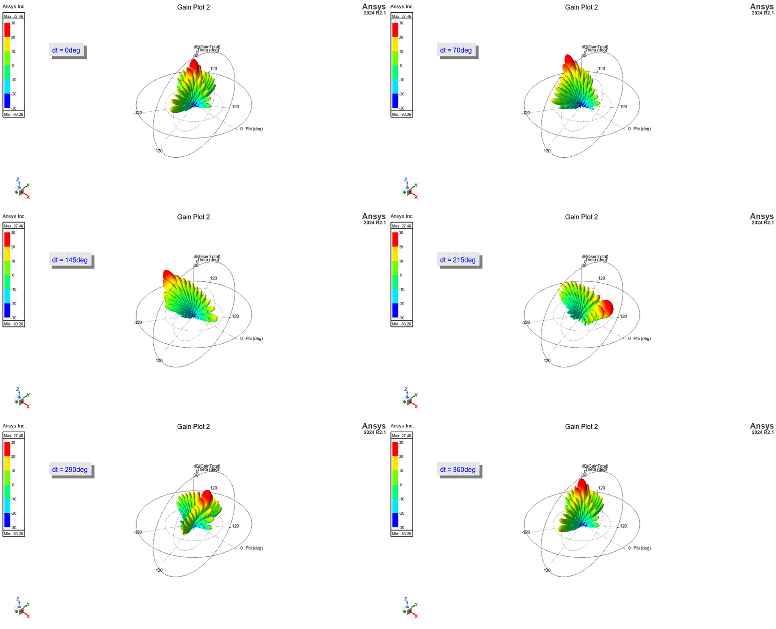
Beamsteering Fun
Pictured here is an animation of the the aforementioned progressive phase shift. While the real array I fabricated had to rely on switching feed lines between different lengths of coax, this simulation covers a continuous shift. Additional layout methods were also tested, but as to be expected the linear method with CoCo worked best. Github with additional instructions to assemble, rad patterns, and other photos, coming soon…
Array simulation of L-Band antenna below, to be added here after HFSS finishes the simulation.
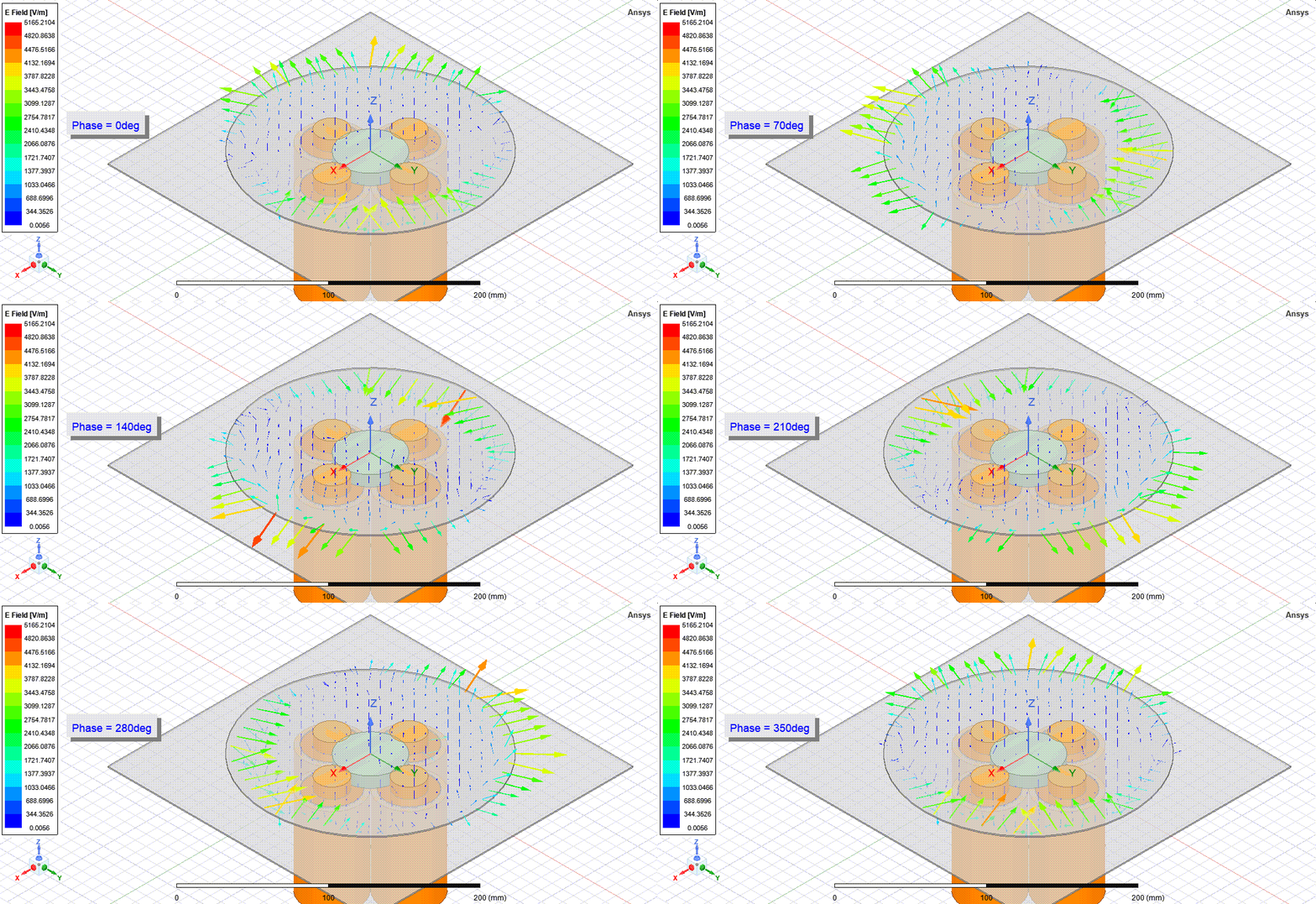
L-Band Circularly Polarized Patch Antenna Element
Built as part of a final project for my phased array course, this is a custom design that iterates on general principles of circularly polarized patches, but utilizes 4 offset feeds to enforce the circular nature of it. Intended to be fed by either a butler matrix or a saleh power divider that applies a progressive 90 degree phase shift through structural composition. Currently I am building one for use at 915[MHz] as a base station to pair with a model rocket.
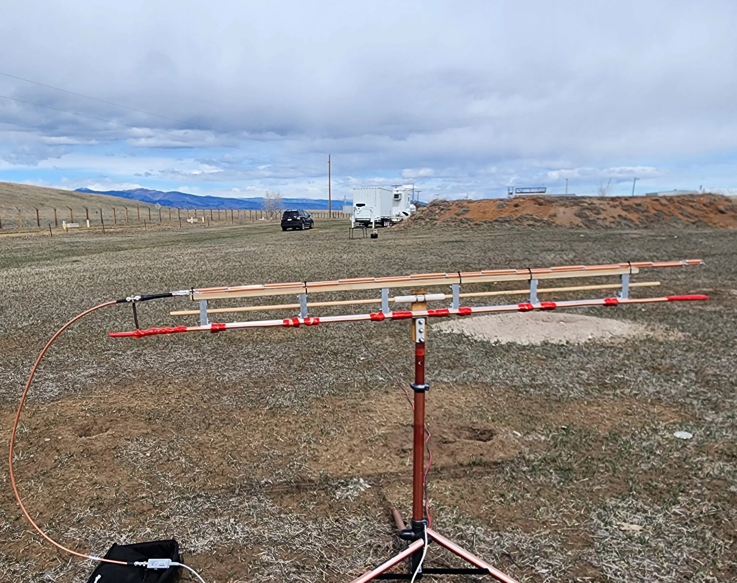
Coaxial Collinear Antenna Element
Created as a cheap, easily sourced, and high gain element, the CoCo antenna I designed for the Windprofilers at UCAR were designed with the idea of modularity as the focus. During many field deployments, the majority of time and money was spent dancing around the deployment of the heaviest or bulkiest systems, this aimed to create a streamlined AESA we could deploy with 1-2 technicians from the back of a truck. The main limitations of the design being that It needed to fit inside a 8ft² square, and avoid the potential for debris, water, or snow to pile ontop the antennas (as to why CoCo was used).
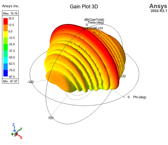
Radiation Pattern of a Single Coaxial Collinear Element
This initial simulation provided the proof of concept that would later become the array, along with the many element iterations that would soon follow. By utilizing HFSS’s tuning/iterative machine learning systems, I was able to tune the feeds in a way to better balance the direction of radiation, as an end-fed system had an inherent skew in the direction opposite of the feed. Later I would half this design and incorporate the matching network and power splitting into a center-fed pcb with two of these elements as arms. Sacrificing some gain in the broadside for overall system ease of use as well as tuning.
