Modular 915 [MHz] Coaxial Collinear Active electronically steered Array
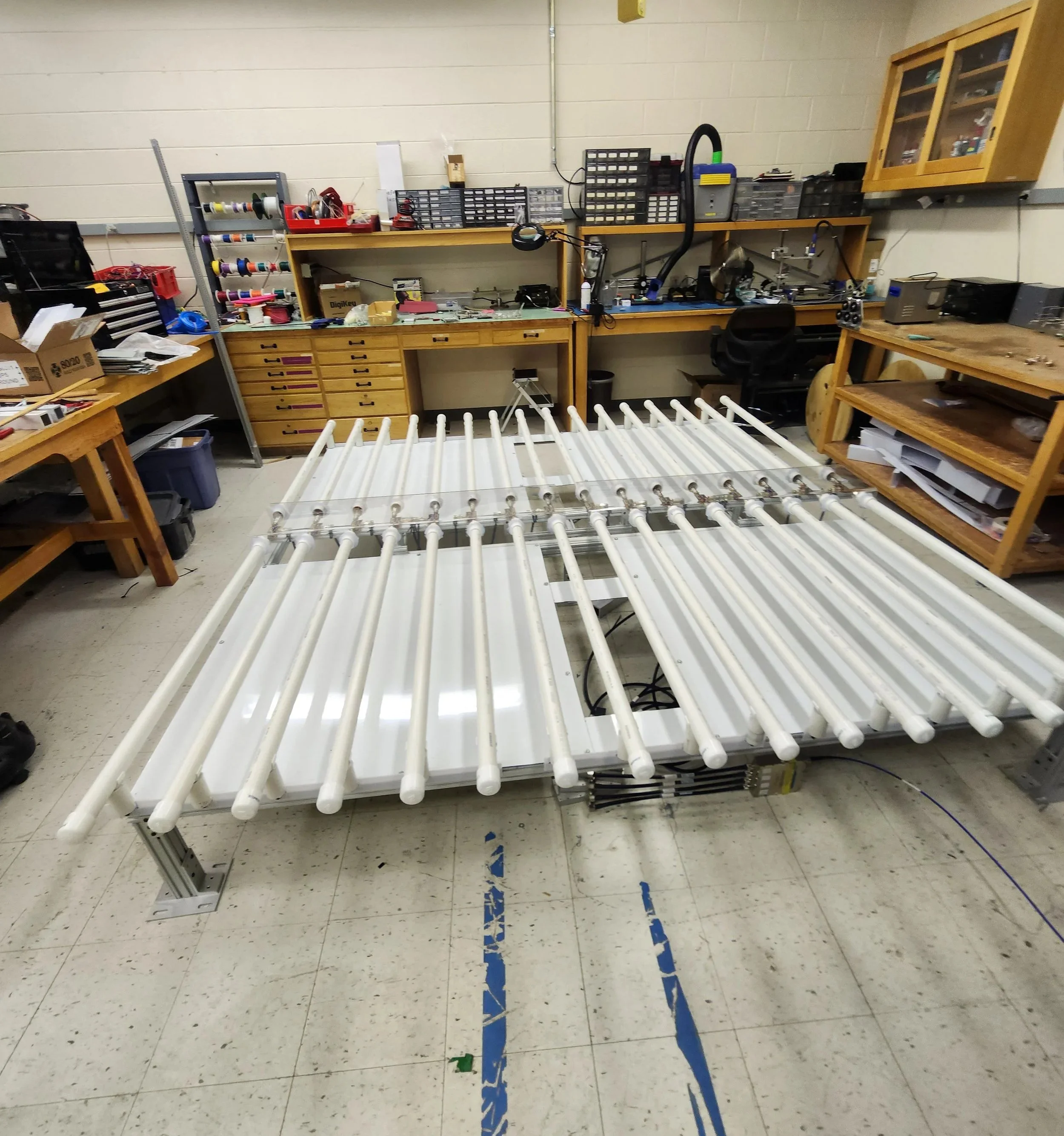
Prototype CoCo Linear AESA at 915[MHz]
The modular 915[MHz] CoCo AESA is the culmination of my introduction to RF and Radar systems. From the start, the idea was to make a radar that any technician could easily repair, with each part of the radar being easily sourced or fabricated from open source schematics and designs. The idea being that any organization could hand-fabricate most of the parts of the system with readily available materials at reasonable cost. Having worked for weather research organizations, the overall lack of funding creating a dire need for modern systems that could be updated and repaired far into the future, potentially even upgraded as well.
To summarize the overall design, the 915[MHz] Coaxial Collinear Active Electronically Steered Array Wind Profiling System is a planar scanning phased array. Measuring the doppler speeds by reflecting radiation bouncing off of wind eddy currents in the atmosphere. Initial design goals were for the system to only comprise the antenna and work as a drop-in replacement for a Vaisala LAP3000 system’s antenna, as the patch antenna array it uses was degrading. However additional developments added increasing functionality independent of the retrofit system.
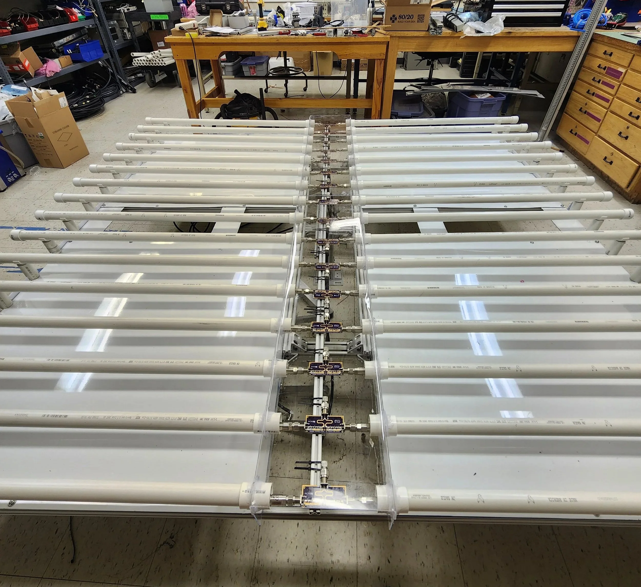
The AESA design is based off of ancient designs made by NOAA, that utilized an array of coaxial collinear antennas to achieve high vertical gain. My main differentiation being the unique balancing, matching, and tuning of inter-element dimensions and feed methods. This system is comprised of 2 sets of 16 antenna elements with two separate 8-section Coaxial Collinear Antennas on either side, that operate as independently steered linear arrays for X and Y steering. The steering aspect itself implemented as a cascade of switches that adjust the phase by a fixed amount. This gives it the ability to add a fixed progressive phase shift that chose positive or negative pointing along a chosen axis. The fabricated and tested system able to utilize a progressive 90 degree phase shift that could steer ± 20 degrees in cardinal directions.
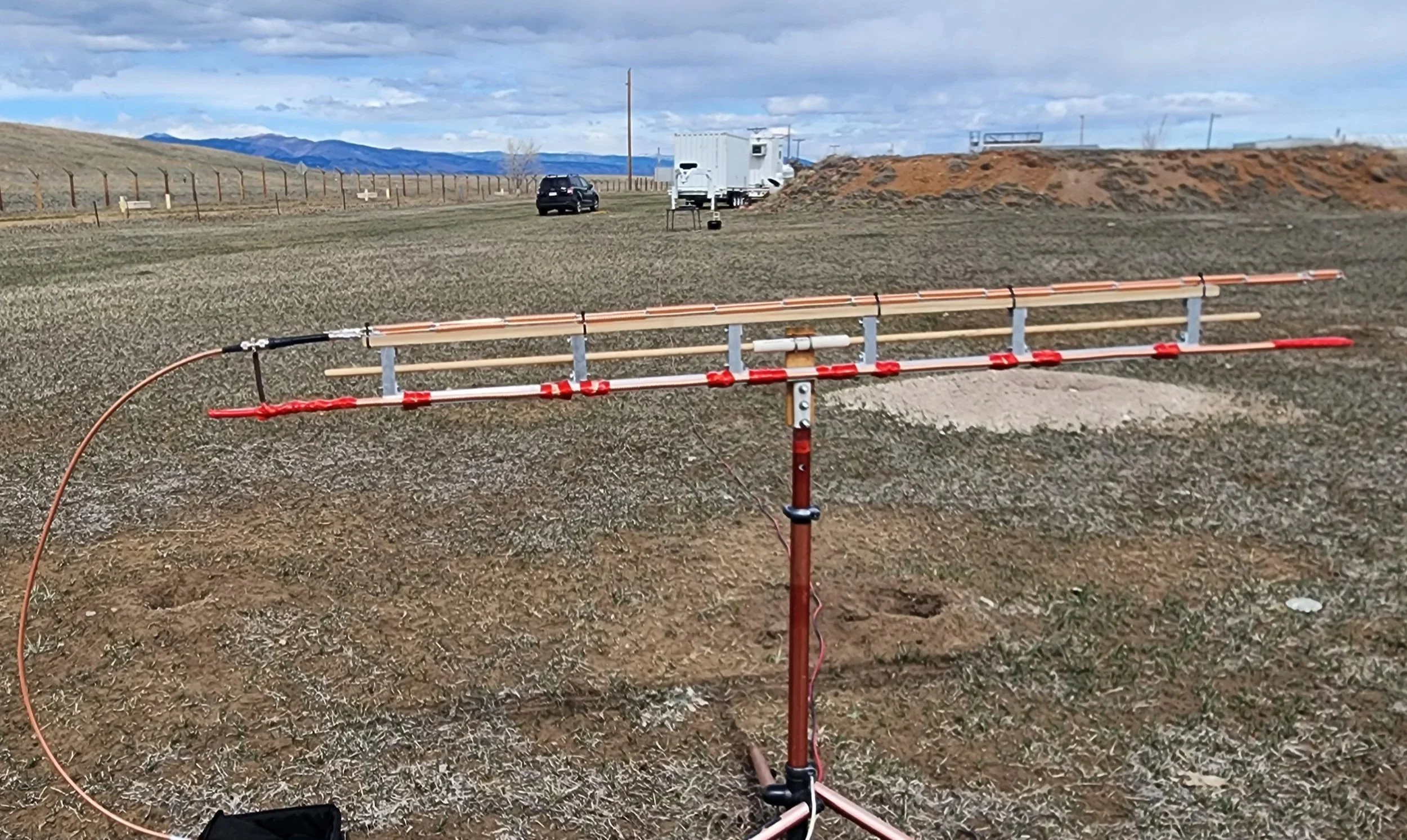
The Coaxial Collinear Element
In the design of the Coaxial Collinear elements themselves, many iterative and tuned simulations completed with Ansys HFSS and subsequently verified with Matlab, allowed me to adjust a variety of real world parameters before initiating any fabrication. Initial versions when fabricated, were far more flexible than originally anticipated, prompting a second iteration that comprised of two separate arms, each an 8-section end-fed coco antenna that attached to either end of a Balun/Matching Network/Power Divider PCB that could more easily be mounted, fed, tuned, and matched with minimal losses.
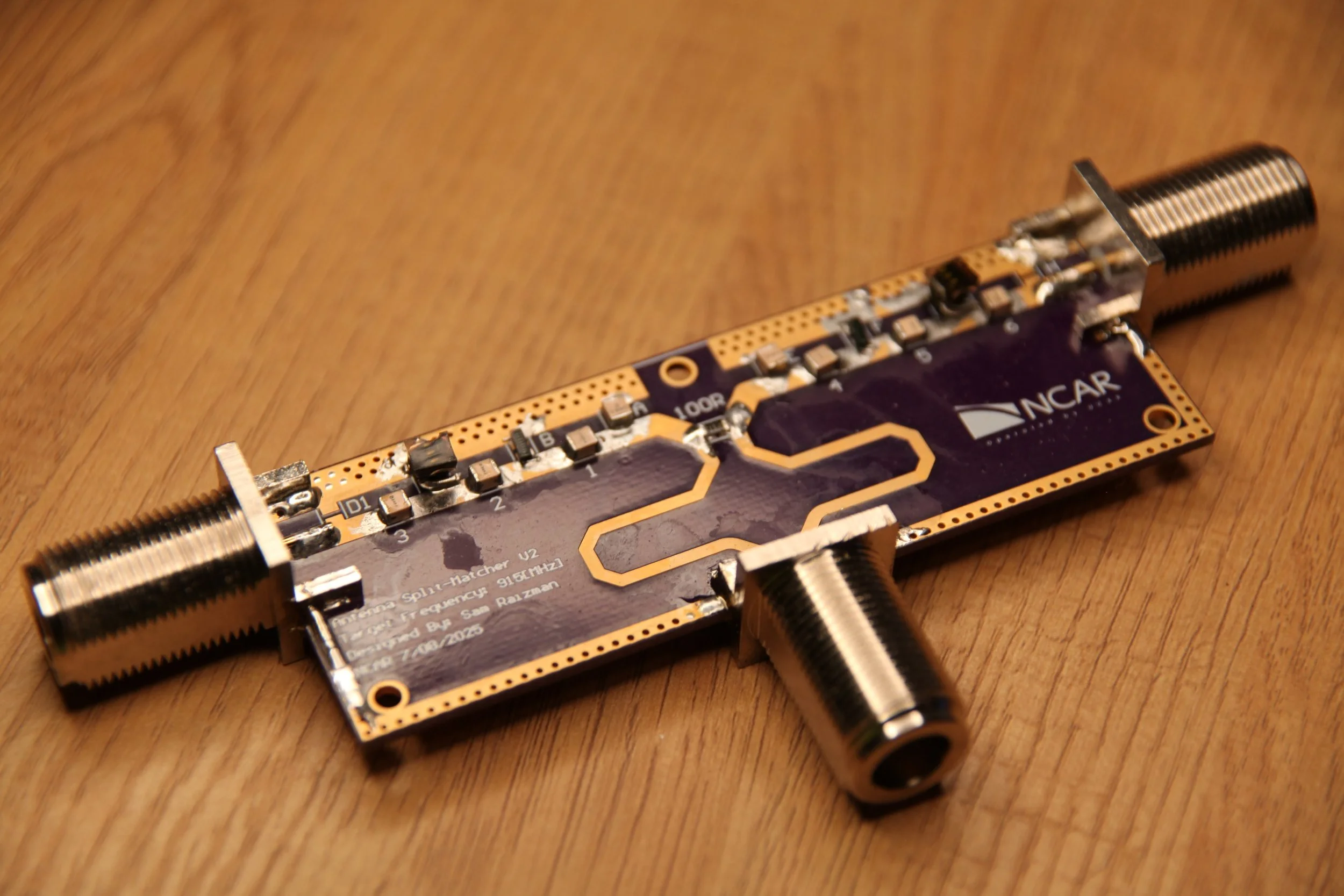
The Matching Network and Balancer
As soldering together a balun by hand with coax cable is rather messy and imprecise, I chose to build an easily tuned Wilkinson power divider, each arm needing to be tuned independently and then as a whole together with both arms. This had to unfortunately be done by me 16+ times.
The AESA Coming Together
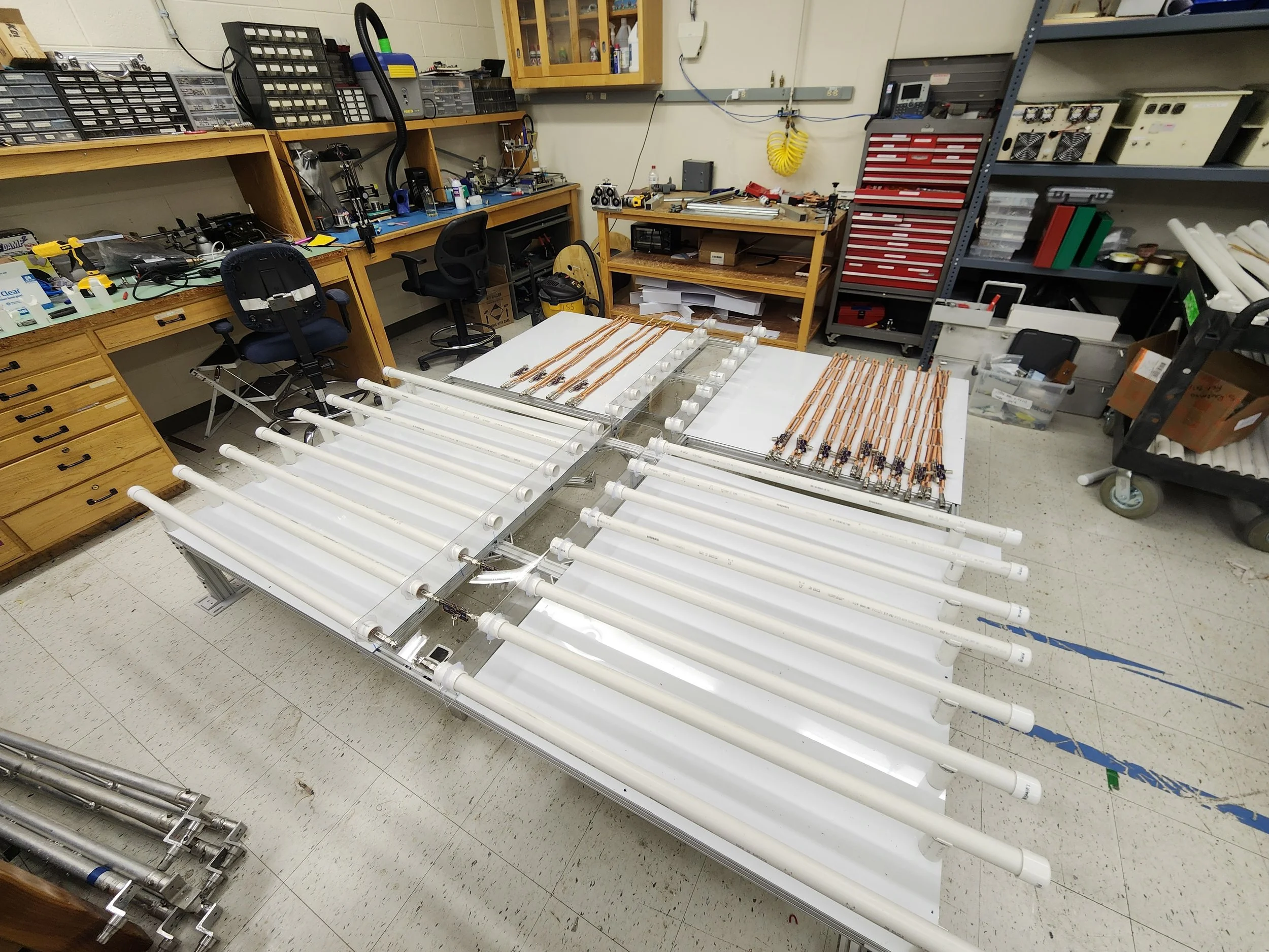
Initially, 4 of these two-arm antennas were built and verified against simulation data, and with enough confirmation on the function, it was time to test a full linear array with steering. With all 16 elements (32 antennas and 16 Baluns) of one of the two linear arrays fabricated, and then tuned/matched/balanced to 50 ohms at 915[MHz], I had enough to begin implementation and testing of the AESA capabilities in regards to beam steering. The physical shifting was achieved by creating 4 separate channels with 1x, 2x, 3x, and 4x progressive phase shifts completed 360 degrees of shifting every 4 elements. This was achieved via phase and length matching each pathway, while also tuning attenuation levels to match at the output. each line with an isolated bypass channel for direct vertical pointing of the beam. The 16 tuned outputs then feeding all 16 elements from the single feed for the radar’s high power amplifiers.
The radar chain itself being the simplest as it utilized an FPGA based DDS SDR that would create the IF, which was then filtered, amplified, and mixed with an LO, which then would be shot through a high power 60dB amplifier into the beam splitting network previously described. All of these systems were then mounted along with the antennas onto a prototype 8ft² 8020 aluminum channeled prototyping frame I designed and hand-fabricated.
Finally, both the antenna and the complete system was tested by implementing custom antenna ranging software in python that spun the entire array with respect to a stationary custom continuous wave transmitter putting out 915[MHz] signals. By varying the fixed transmitter’s vertical location, limited by height restrictions and funding, we were able to validate the proof of concept design. This was then used to successfully collect test data from an existing Vaisala system that it would retrofit. The goal being to make the CoCo AESA able to slot into the rectangular-patch-based square planar array that Vaisala utilized. We verified functional operation able of the beam steering, along with the peak gain at the steered angles aligning with my simulations at only around 5-10% less gain. The steered angles being more lossy than the straight vertical pointing. Unfortunately, the basic verification was all that could be performed before I departed UCAR, however I left them with the full system capable of measuring EIRP at steered angles via the test setup I had built. All it required was the physical running of the software should they want to generate a 3D radiation pattern to directly compare to simulations.
Future plans also included: decreasing frame weight and size to optimize performance, transferring the beam forming network into a butler matrix PCB that could be swapped easily without tuning, transferring the entire radar system from SDR input to mixed 915[MHz] output onto a PCB that could be ordered independently, and ultimately developing an S-Band version of this array. Unfortunately for the system however, this was also when I departed UCAR as I had completed my masters and a new focus by leadership that shifted organization goals from new development and design, to buying premade off-the-shelf systems. The exact problem that the design was being made to combat. The simulations I am allowed to share have been included below.
